最近开始准备从头开始实现一个FM的调制月解调的实验,在进行这些实验之前,首先需要进行的一个操作就是读取SD卡当中的文件,将SD卡当中的文件读取到内存当中,在FPGA的PL端实现将数据读出,并且将读取出来的数据提供给PCM模块.这样PCM模块就能够播放音乐了.
这是实现FM调制的第一步,先有一个音频数据源.
1. 系统结构
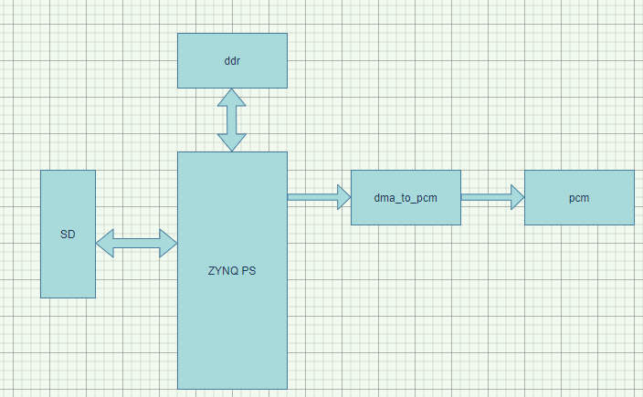
ZYNQ读取SD卡的整个系统架构如下图所示:
在ZYNQ的PS侧,SD卡控制器负责读取SD卡的文件,将读取到的PCM的音频数据写入到内存当中,当音频数据被写入到内存当中之后,将会启动PL端的DMA开始从内存当中将数据进行读出.读出之后的数据给到PCM模块,从而实现音频信号的播放.
在这个系统当中主要需要去实现的也就如下几个东西:
- ZYNQ PS通过Xilinx提供好的API进行SD开内文件的读取
- PL端需要用户实现一个DMA的读取模块,通过AXI接口.
- 将数据从内存当中读取出来之后还需要注意音频模块的驱动,相对来说比较简单.
2. PS读取SD卡文件
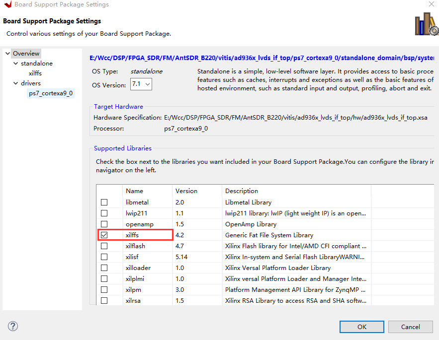
在Xilinx的软件开发工具vitis当中,已经移植好了FAT文件系库,在使用的时候,需要在BSP当中使能这个库就行了.
在读取SD文件或者向SD卡当中写入文件的时候按照一定的步骤来就可以了.
2.1 访问SD卡当中文件的一般步骤
- 挂载SD卡 f_mount()在进行SD卡初始化的时候,只需要简简单单地挂载一下SD卡就可以了.
1
2
3
4
5
FRESULT f_mount (
FATFS* fs, /* Pointer to the filesystem object (NULL:unmount)*/
const TCHAR* path, /* Logical drive number to be mounted/unmounted */
BYTE opt /* Mode option 0:Do not mount (delayed mount), 1:Mount immediately */
)1
2
3
4
5
6
7
8
9
10
11
12
13
14int sd_init()
{
FRESULT ret;
/* define the file path */
TCHAR * file_path = "0:/";
/* mount the sdcard file system */
ret = f_mount(&fat_inst, file_path, 0);
if(ret != FR_OK){
xil_printf("mount sd card failed!!! Error code is %d \r\n", ret);
return ret;
}
return FR_OK;
}- 打开具体的某个文件 f_open()
1
2
3
4
5FRESULT f_open (
FIL* fp, /* Pointer to the blank file object */
const TCHAR* path, /* Pointer to the file name */
BYTE mode /* Access mode and file open mode flags */
)
- 打开具体的某个文件 f_open()
- 移动到文件的具体位置 f_lseek()
1
2
3
4FRESULT f_lseek (
FIL* fp, /* Pointer to the file object */
FSIZE_t ofs /* File pointer from top of file */
) 读写文件 f_write()/f_read()
1
2
3
4
5
6
7
8
9
10
11
12
13FRESULT f_write (
FIL* fp, /* Pointer to the file object */
const void* buff, /* Pointer to the data to be written */
UINT btw, /* Number of bytes to write */
UINT* bw /* Pointer to number of bytes written */
)
FRESULT f_read (
FIL* fp, /* Pointer to the file object */
void* buff, /* Pointer to data buffer */
UINT btr, /* Number of bytes to read */
UINT* br /* Pointer to number of bytes read */
)关闭文件 f_close()
1
2
3FRESULT f_close (
FIL* fp /* Pointer to the file object to be closed */
)基于上面的这些步骤,可以写两个简单的函数,从而实现对SD卡的读写.
1
2
3
4
5
6
7
8
9
10
11
12
13
14
15
16
17
18
19
20
21
22
23
24
25
26
27
28
29
30
31
32
33
34
35
36
37
38
39
40
41
42
43
44
45
46
47
48
49
50
51
52
53
54
55
56
57
58
59
60
61
62
63
64
65
66
67
68
69
70
71
72
73int sd_write(char * file_name, u32 * src_addr, u32 byte_len)
{
FIL file_inst;
FRESULT ret;
UINT byte_write;
/* open a pcm file */
ret = f_open(&file_inst, file_name, FA_READ);
if(ret != FR_OK)
{
xil_printf("Open file failed, the error code is %d\r\n", ret);
return ret;
}
/* move to the begining of the pcm file */
ret = f_lseek(&file_inst, 0);
if(ret != FR_OK)
{
xil_printf("Move to the file beginning failed, the error code is %d\r\n", ret);
return ret;
}
/* Write the data into sd card from ddr */
ret = f_write(&file_inst, (void *)src_addr, (UINT)byte_len, &byte_write);
if(ret != FR_OK)
{
xil_printf("Write file failed, the error code is %d \r\n", ret);
return ret;
}
/* close the file */
ret = f_close(&file_inst);
if(ret != FR_OK)
{
xil_printf("close the file failed, the error code is %d\r\n", ret);
return ret;
}
return FR_OK;
}
int sd_read(char * file_name, u32 * dist_addr, u32 byte_len)
{
FIL file_inst;
FRESULT ret;
UINT byte_read;
/* open a pcm file */
ret = f_open(&file_inst, file_name, FA_READ);
if(ret != FR_OK)
{
xil_printf("Open file failed, the error code is %d\r\n", ret);
return ret;
}
/* move to the begining of the pcm file */
ret = f_lseek(&file_inst, 0);
if(ret != FR_OK)
{
xil_printf("Move to the file beginning failed, the error code is %d\r\n", ret);
return ret;
}
/* Read the data from sd card into ddr */
ret = f_read(&file_inst, (void *)dist_addr, (UINT)byte_len, &byte_read);
if(ret != FR_OK)
{
xil_printf("Read file failed, the error code is %d \r\n", ret);
return ret;
}
/* close the file */
ret = f_close(&file_inst);
if(ret != FR_OK)
{
xil_printf("close the file failed, the error code is %d\r\n", ret);
return ret;
}
return FR_OK;
}3. AXI 读取内存数据
在PS端读取了SD卡的文件并且将数据写入到内存当中之后,在PL端就可开始将数据读出了,在这里需要使用AXI接口,AXI接口已经使用过很多次了,不需要再详细说了.只不过再读取数据的时候需要注意一个字节序的问题.也就是数据在SD卡中存储的形式和读取到DDR当中之后再写入到FIFO当中需要注意的字节序的问题.
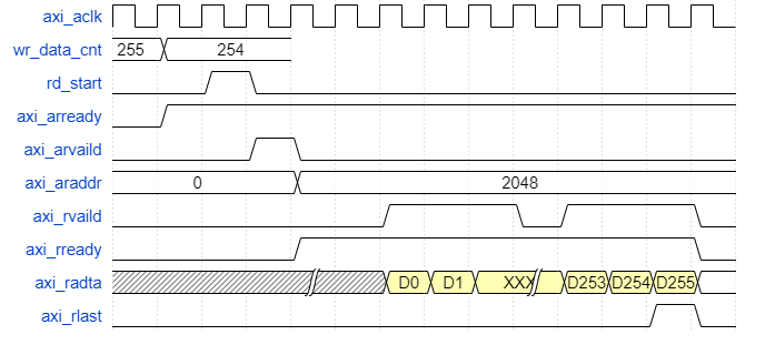
AXI的时序设计如下图所示,没什么好说的,就是标标准准的AXI时序就可以了.
1
2
3
4
5
6
7
8
9
10
11
12
13
14
15
16
17
18
19
20
21
22
23
24
25
26
27
28
29
30
31
32
33
34
35
36
37
38
39
40
41
42
43
44
45
46
47
48
49
50
51
52
53
54
55
56
57
58
59
60
61
62
63
64
65
66
67
68
69
70
71
72
73
74
75
76
77
78
79
80
81
82
83
84
85
86
87
88
89
90
91
92
93
94
95
96
97
98
99
100
101
102
103
104
105
106
107
108
109
110
111
112
113
114
115
116
117
118
119
120
121
122
123
124
125
126
127
128
129
130
131
132
133
134
135
136
137
138
139
140
141
142
143
144
145
146
147
148
149
150
151
152
153
154
155
156
157
158
159
160
161
162
163
164
165
166
167
168
169
170
171always @(posedge M_AXI_ACLK)begin
if (M_AXI_ARESETN == 0 ) begin
init_txn_ready <= 1'b0;
end
else if((!init_txn_ff2) && init_txn_ff)begin
init_txn_ready <= 1'b1;
end
end
//----------------rd_start------------------
always @(posedge M_AXI_ACLK)begin
if (M_AXI_ARESETN == 0 ) begin
rd_start <= 1'b0;
end
// the fifo don't have enought data, and the axi bus is idle, start to get data from ddr
else if(init_txn_ready == 1'b1 && wr_data_count <= 'd2 && axi_arvalid == 1'b0 && axi_rready == 1'b0)begin
rd_start <= 1'b1;
end
else begin
rd_start <= 1'b0;
end
end
//----------------axi_arvalid------------------
always @(posedge M_AXI_ACLK)begin
if (M_AXI_ARESETN == 0 ) begin
axi_arvalid <= 1'b0;
end
// read addr command is accepted
else if (axi_arvalid == 1'b1 && M_AXI_ARREADY == 1'b1) begin
axi_arvalid <= 1'b0;
end
// start to read data from ddr
else if(rd_start == 1'b1)begin
axi_arvalid <= 1'b1;
end
end
//----------------axi_araddr------------------
always @(posedge M_AXI_ACLK)begin
if (M_AXI_ARESETN == 0 ) begin
axi_araddr <= 'd0;
end
// read addr command is accepted, and the address is reach to the maximum offset
else if (axi_arvalid == 1'b1 && M_AXI_ARREADY == 1'b1 && (axi_araddr == (pcm_end_address - ADDR_OFFSET))) begin
axi_araddr <= 'd0;
end
// read addr command is accepted
else if (axi_arvalid == 1'b1 && M_AXI_ARREADY == 1'b1) begin
axi_araddr <= axi_araddr + ADDR_OFFSET;
end
end
//----------------axi_rready------------------
always @(posedge M_AXI_ACLK)begin
if (M_AXI_ARESETN == 0 ) begin
axi_rready <= 1'b0;
end
// when the burst is done, stop to receive data from axi bus, ready signal should be low
else if (end_cnt_burst == 1'b1) begin
axi_rready <= 1'b0;
end
// read addr command is accepted, start to receive data from axi bus
else if (axi_arvalid == 1'b1 && M_AXI_ARREADY == 1'b1) begin
axi_rready <= 1'b1;
end
end
//----------------cnt_burst------------------
// used to count how many data has be accepted
always @(posedge M_AXI_ACLK ) begin
if (M_AXI_ARESETN == 1'b0) begin
cnt_burst <= 'd0;
end
else if (add_cnt_burst) begin
if(end_cnt_burst)
cnt_burst <= 'd0;
else
cnt_burst <= cnt_burst + 1'b1;
end
end
assign add_cnt_burst = M_AXI_RVALID & axi_rready;
assign end_cnt_burst = add_cnt_burst && cnt_burst == C_M_AXI_BURST_LEN - 1;
//----------------wr_fifo_data/wr_fifo_en------------------
always @(posedge M_AXI_ACLK ) begin
if (M_AXI_ARESETN == 1'b0) begin
wr_fifo_data <= 'd0;
wr_fifo_en <= 1'b0;
end
// the pcm file store the data in a LSB MSB byte order, so that user should change the byte order
else if( M_AXI_RVALID & axi_rready)begin
wr_fifo_en <= 1'b1;
wr_fifo_data <= {M_AXI_RDATA[15:0],M_AXI_RDATA[31:16],M_AXI_RDATA[47:32],M_AXI_RDATA[63:48]};
end
else begin
wr_fifo_en <= 1'b0;
wr_fifo_data <= 'd0;
end
end
tx_dma_fifo inst_tx_dma_fifo (
.rst(~M_AXI_ARESETN), // input wire rst
.wr_clk(M_AXI_ACLK), // input wire wr_clk
.rd_clk(user_clk), // input wire rd_clk
.din(wr_fifo_data), // input wire [63 : 0] din
.wr_en(wr_fifo_en), // input wire wr_en
.rd_en(rd_fifo_en), // input wire rd_en
.dout(rd_fifo_data), // output wire [15 : 0] dout
.full(full), // output wire full
.empty(empty), // output wire empty
.rd_data_count(rd_data_count), // output wire [11 : 0] rd_data_count
.wr_data_count(wr_data_count), // output wire [9 : 0] wr_data_count
.wr_rst_busy(wr_rst_busy), // output wire wr_rst_busy
.rd_rst_busy(rd_rst_busy) // output wire rd_rst_busy
);
//====================================================
// The code below is used for pcm module
//====================================================
//----------------tx_ready------------------
// ready to send data into pcm module
always @(posedge user_clk or negedge M_AXI_ARESETN) begin
if (M_AXI_ARESETN==1'b0) begin
tx_ready <= 'd0;
end
else if (rd_data_count >= 1022) begin
tx_ready <= 1'b1;
end
end
//----------------cnt_div------------------
always @(posedge user_clk or negedge M_AXI_ARESETN) begin
if (M_AXI_ARESETN==1'b0) begin
cnt_div <= 'd0;
end
else if (tx_ready == 1'b1 && cnt_div == div_count - 1) begin
cnt_div <= 'd0;
end
else if (tx_ready == 1'b1) begin
cnt_div <= cnt_div + 1'b1;
end
end
//----------------rd_fifo_en------------------
always @(posedge user_clk or negedge M_AXI_ARESETN) begin
if (M_AXI_ARESETN==1'b0) begin
rd_fifo_en <= 1'b1;
end
else if (tx_ready == 1'b1 && cnt_div == div_count - 1) begin
rd_fifo_en <= 1'b1;
end
else begin
rd_fifo_en <= 1'b0;
end
end
//----------------tx_data/tx_valid------------------
always @(posedge user_clk or negedge M_AXI_ARESETN) begin
if (M_AXI_ARESETN==1'b0) begin
tx_data_r <= 'd0;
tx_vaild_r <= 'd0;
end
else begin
tx_data_r <= rd_fifo_data;
tx_vaild_r <= rd_fifo_en;
end
end