1. 前言
在之前的博客当中记录了如何来检测短训练序列,在检测短训练序列的时候,实现了一系列的模块,这些模块在无线通信的算法里面是比较常用的,在之后的学习当中也将会经常使用到。
检测到短训练序列之后,可以使用短训练序列对接收到的信号进行粗频偏校正,在这篇博客当中,我会记录学习这一部分的内容。
2. 802.11a粗频偏校正原理
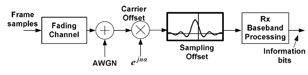
在接收机接收信号的过程如上图所示,在信号传递的过程当中需要经过无线信道,在接收机当中,由于本地载波和采样时钟与数据源端地不一致,从而引入了频偏到信号当中。由于频偏的引入,会对基带信号的处理带来影响,为了需要消除频偏带来的影响。
假设要接接收的信号的中心频率为 $f_c$ , 本地接受到的信号由于频偏可以看做本地使用了一个 $(1+e)f_c $ 的载波去接收信号,根据混频的原理,在接收信号时候将会得到 $(((1+e)f_c)-f_c)$ 和 $ (((1+e)f_c)+f_c) $ ,也即是差频项和倍频项。倍频项可以通过低通滤波器滤除。
这样我们在基带得到的信号就有一个 $ef_c$ 的频偏。频偏校正的目的就是尽量消除 $ef_c$ 所带来的影响。
根据角频率公式 $w = 2\pi f_s$ ;
那么在信号的每个采样周期下得到的弧度变化量是 $\alpha = wT_s = 2\pi f_sT_s $ ;
因此如果我们能够估计出每个采样周期弧度的变化量,那么我们就能够计算出基带信号的频偏。
下图是文献当中关于使用短训练序列进行校正的时候所采取的估计信号的弧度变化量的方法。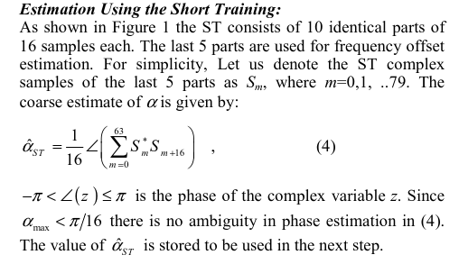
可以看到公式当中对当前采样点的共轭和延时16个采样点之后的数据进行相乘之后进行累加,并求取累加之后的复数的相位,最后将这个相位除以16,得到最终估计的相位。
因为采用的是对当前采样点进行取共轭,因此这个估计出来的相位与实际的方向正好是相反的。
估计出这个相位之后,就可以得到估计出来的频率,将这个频偏叠加到输入的信号上,从而达到校正频偏的作用。
$fe = \alpha{ST}/(2\pi T_s)$ ;
假设输入的信号为 $ S(n)= e^{2\pi fi nT_s}$ ,那么产生的频偏校正信号为 $ S(cfo) = e^{-2\pi f_e nT_S} = e^{-n\alpha{st}}$
3. matlab 验证
1 | %%%%%%%%%%%%%%%%%%%%%%%%%%%%%%%%%%%%%%%%%%%%%%%%%%%%%%%%%%%%%%%%%%%%%%%%%%%%%%%%%%%% |
4. FPGA设计
了解了算法原理之后,就可以进行FPGA的设计了,在上一篇博客当中介绍过,上一篇博客当中实现的那些模块,许多都是能够共用的,因此能够帮助加快设计流程。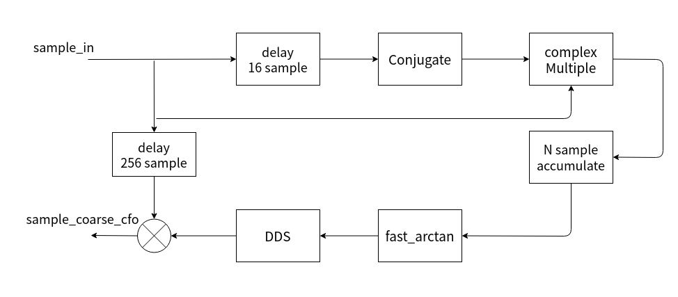
首先进来的采样点先延时16个采样点,然后对延时之后的采样点进行取共轭,然后将延时后的采样点和当前的采样点复数乘法,复数乘法的结果进行16点累加。累加得到的输出经过arctan或者cordic算法实现相位的求取之后。根据所求取的估算的相位,产生一个频率控制字用于驱动DDS粗频偏校正信号。最后将输入的采样点和粗频偏校正信号进行复数乘法之后,得到经过粗频偏校正之后的结果。
4.1 fast arctan算法
在FPGA当中实现三角函数比如反正切arctan这一类的函数是比较困难的,常用的方法是使用cordic算法来进行反正切的计算。当然也有一些常见的用于快速近似计算的方法,在这里推荐两个网站上面介绍了如何使用近似的方法来计算arctan,这对使用FPGA来实现很有意义。
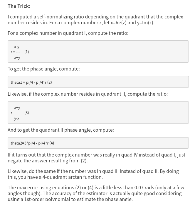
M_PI_4x - x(fabs(x) - 1)(0.2447 + 0.0663fabs(x))
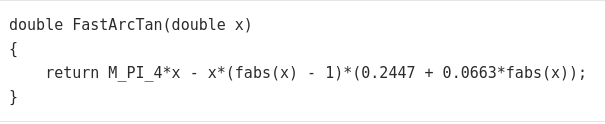
在本篇博客当中,主要实现第二个算法模块,用于实现快速的反正切计算。
也就是 est_alpha = M_PI_4x - x(fabs(x) - 1)(0.2447 + 0.0663fabs(x)); (x=q/i)
该模块的设计思路以及时序如下:
上游模块检测到短训练序列之后,给出检测到短训练序列的的信号的IQ路数据,本模块将会对IQ路数据进行求取相位。
按照上面的公式,首先需要求的IQ信号的结果作为主要公式当中的x的值,然后一次进行多次乘法运算,最终将结果进行一个累加,最终得到输出的相位的值。
上面的时序图中将各个步骤进行了展示,为了减少DSP资源的消耗,在FPGA当中采用对不同的状态进行控制,从而实现只需要一个触发器,一个乘法器就能能够完成上面的算法,为此需要控制计算的状态,在不同的状态下完成不同的计算。
这里的计算过程是计算定点数。
具体的verilog代码如下 :
fix_arctan.v1
2
3
4
5
6
7
8
9
10
11
12
13
14
15
16
17
18
19
20
21
22
23
24
25
26
27
28
29
30
31
32
33
34
35
36
37
38
39
40
41
42
43
44
45
46
47
48
49
50
51
52
53
54
55
56
57
58
59
60
61
62
63
64
65
66
67
68
69
70
71
72
73
74
75
76
77
78
79
80
81
82
83
84
85
86
87
88
89
90
91
92
93
94
95
96
97
98
99
100
101
102
103
104
105
106
107
108
109
110
111
112
113
114
115
116
117
118
119
120
121
122
123
124
125
126
127
128
129
130
131
132
133
134
135
136
137
138
139
140
141
142
143
144
145
146
147
148
149
150
151
152
153
154
155
156
157
158
159
160
161
162
163
164
165
166
167
168
169
170
171
172
173
174
175
176
177
178
179
180
181
182
183
184
185
186
187
188
189
190
191
192
193
194
195
196
197
198
199
200
201
202
203
204
205
206
207
208
209
210
211
212
213
214
215
216
217
218
219
220
221
222
223
224
225
226
227
228
229
230
231
232
233
234
235
236
237
238
239
240
241
242
243
244
245
246
247
248
249
250
251
252
253
254
255
256
257
258
259
260
261
262
263
264
265
266
267
268
269
270
271
272
273
274
275
276
277
278
279
280
281
282
283
284
285
286
287
288
289
290
291
292
293module fix_arctan (
input wire clk ,
input wire rst ,
input wire enable ,
input wire [31:0] y_in , // input q
input wire [31:0] x_in , // input I
input wire xy_in_valid ,
output reg [31:0] angle_out , // angle out of current
output reg angle_out_valid ,
output reg [31:0] angle_out_div16x2pi , // fix point angle out
output reg angle_out_div16x2pi_valid
);
//====================================================
// parameter define
//====================================================
localparam IDLE = 3'd0;
localparam DIV = 3'd1;
localparam XABS = 3'd2;
localparam ABS663 = 3'd3;
localparam XMABS = 3'd4;
localparam XMABS2 = 3'd5;
localparam M_PI_4 = 3'd6;
localparam MULT_LAST= 3'd7;
localparam FIX_ONE = 32'd268435456;
localparam FIX_QUART_PI = 32'd210828714;
localparam FIX_P2447 = 32'd65686156;
localparam FIX_P0663 = 32'd17797270;
localparam FIX_DIV2PIX16= 32'd2670176;
//====================================================
// internalsignals and registers
//====================================================
reg [2:0] state ;
reg xy_in_valid_r ;
reg [31:0] x_in_r ;
reg [31:0] y_in_r ;
wire div_out_valid ;
wire [63:0] div_out ;
reg [31:0] fix_div_out ; // 1 bit sign, 3 bit quotient, 28 bit fractional
reg fix_div_out_valid ;
reg [31:0] abs_div ;
reg [31:0] abs_div_minus_1 ;
reg abs_div_valid ;
reg [31:0] mult_in_a ;
reg [31:0] mult_in_b ;
reg mult_in_valid ;
wire [63:0] mult_out ;
reg [2:0] mult_in_valid_dly ;
wire mult_out_valid ;
reg abs663_valid ;
reg [31:0] abs663_plus_p2447 ;
reg xmabs_valid ;
reg [31:0] xmabs_data ;
reg xmabs2_valid ;
reg [31:0] xmabs2_data ;
reg xmquart_pi_valid ;
reg [31:0] xmquart_pi_data ;
always @(posedge clk ) begin
if (rst==1'b1) begin
x_in_r <= 'd0;
y_in_r <= 'd0;
end
else if(xy_in_valid == 1'b1)begin
x_in_r <= (x_in==0)? 1: x_in;
y_in_r <= y_in;
end
end
always @(posedge clk ) begin
if (rst==1'b1) begin
xy_in_valid_r <= 1'b0;
end
else begin
xy_in_valid_r <= xy_in_valid;
end
end
//----------------state------------------
always @(posedge clk ) begin
if (rst==1'b1) begin
state <= IDLE;
end
else begin
case(state)
IDLE : begin
if(enable == 1'b1 && xy_in_valid == 1'b1)begin
state <= DIV;
end
end
DIV : begin
if(fix_div_out_valid == 1'b1)begin
state <= XABS;
end
end
XABS : begin
if(abs_div_valid == 1'b1)begin
state <= ABS663;
end
end
ABS663 : begin
if (abs663_valid == 1'b1) begin
state <= XMABS;
end
end
XMABS : begin
if (xmabs_valid == 1'b1) begin
state <= XMABS2;
end
end
XMABS2 : begin
if (xmabs2_valid == 1'b1) begin
state <= M_PI_4;
end
end
M_PI_4 : begin
if (xmquart_pi_valid == 1'b1) begin
state <= MULT_LAST;
end
end
MULT_LAST: begin
if(angle_out_div16x2pi_valid)begin
state <= IDLE;
end
end
default : state <= IDLE;
endcase
end
end
div_gen_tb u_div_gen_tb (
.aclk(clk), // input wire aclk
.s_axis_divisor_tvalid(xy_in_valid_r), // input wire s_axis_divisor_tvalid
.s_axis_divisor_tdata(x_in_r), // input wire [31 : 0] s_axis_divisor_tdata
.s_axis_dividend_tvalid(xy_in_valid_r), // input wire s_axis_dividend_tvalid
.s_axis_dividend_tdata(y_in_r), // input wire [31 : 0] s_axis_dividend_tdata
.m_axis_dout_tvalid(div_out_valid), // output wire m_axis_dout_tvalid
.m_axis_dout_tdata(div_out) // output wire [47 : 0] m_axis_dout_tdata
);
//----------------fix_div_out------------------
always @(posedge clk ) begin
if (rst==1'b1) begin
fix_div_out <= 'd0;
end
else if (enable == 1'b1) begin
// 1 bit sign, 3 bit quotient, 28 bit fractional
fix_div_out <= {div_out[63], div_out[34:32], 28'd0} + {{4{div_out[31]}},div_out[30:3]};
end
end
//----------------fix_div_out_valid------------------
always @(posedge clk ) begin
fix_div_out_valid <= div_out_valid;
abs_div_valid <= fix_div_out_valid;
end
//----------------abs_div------------------
always @(posedge clk ) begin
if (rst==1'b1) begin
abs_div <= 'd0;
abs_div_minus_1 <= 'd0;
end
else if (fix_div_out_valid == 1'b1) begin
abs_div <= fix_div_out[31] ? (~fix_div_out)+1: fix_div_out ;
abs_div_minus_1 <= fix_div_out[31] ? (~fix_div_out)+1 - FIX_ONE: fix_div_out - FIX_ONE;
end
end
//----------------mult_in_valid------------------
always @(posedge clk ) begin
if (rst==1'b1) begin
mult_in_valid <= 1'b0;
mult_in_a <= 'd0;
mult_in_b <= 'd0;
end
else if (state == XABS && abs_div_valid == 1'b1) begin
mult_in_valid <= 1'b1;
mult_in_a <= abs_div;
mult_in_b <= FIX_P0663;
end
else if (state == ABS663 && abs663_valid == 1'b1) begin
mult_in_valid <= 1'b1;
mult_in_a <= abs_div_minus_1;
mult_in_b <= fix_div_out;
end
else if (state == XMABS && xmabs_valid == 1'b1) begin
mult_in_valid <= 1'b1;
mult_in_a <= xmabs_data;
mult_in_b <= abs663_plus_p2447;
end
else if (state == XMABS2 && xmabs2_valid == 1'b1) begin
mult_in_valid <= 1'b1;
mult_in_a <= fix_div_out;
mult_in_b <= FIX_QUART_PI;
end
else if (state == MULT_LAST && angle_out_valid == 1'b1) begin
mult_in_valid <= 1'b1;
mult_in_a <= FIX_DIV2PIX16;
mult_in_b <= angle_out;
end
else begin
mult_in_valid <= 1'b0;
end
end
always @(posedge clk) begin
mult_in_valid_dly <= {mult_in_valid_dly[1:0], mult_in_valid};
end
assign mult_out_valid = mult_in_valid_dly[2];
mult_fix_arctan u_mult_fix_arctan (
.CLK(clk), // input wire CLK
.A(mult_in_a), // input wire [31 : 0] A
.B(mult_in_b), // input wire [31 : 0] B
.P(mult_out) // output wire [63 : 0] P
);
//----------------abs663_plus_p2447------------------
always @(posedge clk ) begin
if (rst==1'b1) begin
abs663_plus_p2447 <= 'd0;
abs663_valid <= 1'b0;
xmabs_data <= 'd0;
xmabs_valid <= 1'b0;
xmabs2_data <= 'd0;
xmabs2_valid <= 1'b0;
xmquart_pi_data <= 'd0;
xmquart_pi_valid <= 1'b0;
angle_out_div16x2pi <= 'd0;
angle_out_div16x2pi_valid <= 1'b0;
end
else if (state == ABS663 && mult_out_valid == 1'b1) begin
abs663_plus_p2447 <= {mult_out[63], mult_out[58:56], mult_out[55:28]} + FIX_P2447;
abs663_valid <= 1'b1;
end
else if (state == XMABS && mult_out_valid == 1'b1) begin
xmabs_data <= {mult_out[63], mult_out[58:56], mult_out[55:28]};
xmabs_valid <= 1'b1;
end
else if (state == XMABS2 && mult_out_valid == 1'b1) begin
xmabs2_data <= {mult_out[63], mult_out[58:56], mult_out[55:28]};
xmabs2_valid <= 1'b1;
end
else if (state == M_PI_4 && mult_out_valid == 1'b1) begin
xmquart_pi_data <= {mult_out[63], mult_out[58:56], mult_out[55:28]};
xmquart_pi_valid <= 1'b1;
end
else if (state == MULT_LAST && mult_out_valid == 1'b1) begin
angle_out_div16x2pi <= {mult_out[63], mult_out[58:56], mult_out[55:28]};
angle_out_div16x2pi_valid <= 1'b1;
end
else begin
abs663_valid <= 1'b0;
xmabs_valid <= 1'b0;
xmabs2_valid <= 1'b0;
xmquart_pi_valid <= 1'b0;
angle_out_div16x2pi_valid <= 1'b0;
end
end
always @(posedge clk ) begin
if (rst==1'b1) begin
angle_out <= 'd0;
angle_out_valid <= 1'b0;
end
else if (xmquart_pi_valid ==1'b1 ) begin
angle_out <= xmquart_pi_data - xmabs2_data;
angle_out_valid <= 1'b1;
end
else begin
angle_out_valid <= 1'b0;
end
end
endmodule
4.2 粗频偏校正
在上一步计算出估计的相位之后,就可以根据这个计算出来的相位产生一个频率控制字,从而实现输出一个校正的信号,叠加到原始信号上,从而实现粗频偏校正。
具体的步骤,就如上面的图中所示:1
2
3
4
5
6
7
8
9
10
11
12
13
14
15
16
17
18
19
20
21
22
23
24
25
26
27
28
29
30
31
32
33
34
35
36
37
38
39
40
41
42
43
44
45
46
47
48
49
50
51
52
53
54
55
56
57
58
59
60
61
62
63
64
65
66
67
68
69
70
71
72
73
74
75
76
77
78
79
80
81
82
83
84
85
86
87
88
89
90
91
92
93
94
95
96
97
98
99
100
101
102
103
104
105
106
107
108
109
110
111
112
113
114
115
116
117
118
119
120
121
122
123
124
125
126
127
128
129
130
131
132
133
134
135
136
137
138
139
140
141
142
143
144
145
146
147
148
149
150
151
152
153
154
155
156
157
158
159
160
161
162
163
164
165
166
167
168
169
170
171module rx_coarse_sync_with_st (
input wire clk ,
input wire rst ,
input wire enable ,
input wire [15:0] sample_in_i ,
input wire [15:0] sample_in_q ,
input wire sample_in_valid ,
input wire [31:0] sts_coarse_freq_offset_i ,
input wire [31:0] sts_coarse_freq_offset_q ,
input wire sts_coarse_freq_offset_valid,
output reg [15:0] sample_cfoc_i ,// data after coarse freq offset
output reg [15:0] sample_cfoc_q ,
output reg sample_cfoc_valid
);
//====================================================
// internal signals and registers
//====================================================
wire sample_delay_out_valid ;
wire [15:0] sample_delay_out_i, sample_delay_out_q;
reg [15:0] sample_delay_out_i_dly, sample_delay_out_q_dly;
// fix point data 1bit sign, 3bit quotient, 28bit fractional
wire [31:0] angle_out ; // actual estimate angle data
wire angle_out_valid ;
wire [31:0] angle_out_div16x2pi ; // estimate angle data for drive dds
wire angle_out_div16x2pi_valid ;
reg [31:0] freq_control_word ;
reg [31:0] phase_accumulator ;
reg phase_acc_valid ;
wire [15:0] dds_cfoc_i, dds_cfoc_q ;
wire dds_cfoc_valid ;
wire cmpy_cfoc_out_valid ;
wire [31:0] cmpy_cfoc_out_i, cmpy_cfoc_out_q;
// delay input samples, after coarse freq offset is calculated out,
// correction freq could add to these samples
sample_delay#(
.DATA_WIDTH ( 32 ),
.DELAY_DEEPTH ( 256 )
)u_sample_delay(
.clk ( clk ),
.rst ( rst ),
.enable ( enable ),
.sample_in_valid ( sample_in_valid ),
.sample_in ( {sample_in_q, sample_in_i} ),
.sample_delay_out_valid ( sample_delay_out_valid ),
.sample_delay_out ( {sample_delay_out_q, sample_delay_out_i})
);
fix_arctan u_fix_arctan(
.clk ( clk ),
.rst ( rst ),
.enable ( enable ),
.y_in ( sts_coarse_freq_offset_q ),
.x_in ( sts_coarse_freq_offset_i ),
.xy_in_valid ( sts_coarse_freq_offset_valid),
.angle_out ( angle_out ),
.angle_out_valid ( angle_out_valid ),
.angle_out_div16x2pi ( angle_out_div16x2pi ),
.angle_out_div16x2pi_valid ( angle_out_div16x2pi_valid )
);
always @(posedge clk ) begin
if (rst==1'b1) begin
freq_control_word <= 'd0;
end
else if (enable == 1'b1) begin
freq_control_word <= {angle_out_div16x2pi, 4'd0};
end
else begin
freq_control_word <= 'd0;
end
end
always @(posedge clk ) begin
if (rst==1'b1) begin
phase_accumulator <= 'd0;
end
else if (enable == 1'b1) begin
if (sample_delay_out_valid == 1'b1) begin
phase_accumulator <= phase_accumulator - freq_control_word;
end
end
else begin
phase_accumulator <= 'd0;
end
end
//----------------phase_acc_valid------------------
always @(posedge clk) begin
if (rst==1'b1) begin
phase_acc_valid <= 1'b0;
end
else if (enable == 1'b1 && sample_delay_out_valid == 1'b1) begin
phase_acc_valid <= 1'b1;
end
else begin
phase_acc_valid <= 1'b0;
end
end
always @(posedge clk) begin
{sample_delay_out_i_dly, sample_delay_out_q_dly} <= {sample_delay_out_i, sample_delay_out_q};
end
// 1 beat latency
dds_cfoc u_dds_cfoc (
.aclk(clk), // input wire aclk
.s_axis_phase_tvalid(phase_acc_valid), // input wire s_axis_phase_tvalid
.s_axis_phase_tdata({ {4{phase_accumulator[31]}},phase_accumulator[31:20]}), // input wire [15 : 0] s_axis_phase_tdata
.m_axis_data_tvalid(dds_cfoc_valid), // output wire m_axis_data_tvalid
.m_axis_data_tdata({dds_cfoc_q, dds_cfoc_i}) // output wire [31 : 0] m_axis_data_tdata
);
cmpy_cfoc u_cmpy_cfoc (
.aclk(clk), // input wire aclk
.s_axis_a_tvalid(dds_cfoc_valid), // input wire s_axis_a_tvalid
.s_axis_a_tdata({dds_cfoc_q, dds_cfoc_i}), // input wire [31 : 0] s_axis_a_tdata
.s_axis_b_tvalid(dds_cfoc_valid), // input wire s_axis_b_tvalid
.s_axis_b_tdata({sample_delay_out_q_dly, sample_delay_out_i_dly}), // input wire [31 : 0] s_axis_b_tdata
.m_axis_dout_tvalid(cmpy_cfoc_out_valid), // output wire m_axis_dout_tvalid
.m_axis_dout_tdata({cmpy_cfoc_out_q, cmpy_cfoc_out_i}) // output wire [63 : 0] m_axis_dout_tdata
);
//----------------sample_cfoc_valid------------------
always @(posedge clk ) begin
if (rst==1'b1) begin
sample_cfoc_valid <= 1'b0;
end
else if (enable == 1'b1) begin
sample_cfoc_valid <= cmpy_cfoc_out_valid;
// sample_cfoc_valid <= sample_delay_out_valid;
end
else begin
sample_cfoc_valid <= 'd0;
end
end
//----------------sample_cfoc_i/q------------------
always @(posedge clk ) begin
if (rst==1'b1) begin
sample_cfoc_i <= 'd0;
sample_cfoc_q <= 'd0;
end
else if (enable == 1'b1) begin
sample_cfoc_i <= {cmpy_cfoc_out_i[31],cmpy_cfoc_out_i[26:12]};
sample_cfoc_q <= {cmpy_cfoc_out_q[31],cmpy_cfoc_out_q[26:12]};
// sample_cfoc_i <= sample_delay_out_i;
// sample_cfoc_q <= sample_delay_out_q;
end
else begin
sample_cfoc_i <= 'd0;
sample_cfoc_q <= 'd0;
end
end
endmodule