0%

OFDM_802.11a学习----星座图映射与循环前缀

1. 前言

在上一篇博客当中,已经完成了数据域的交织,数据域的数据经过交织之后,下一步就是需要对交织之后的bit进行星座图的映射了。
64QAM

2. 调制

在 ofdm 通信系统中根据不同的速率要求,其子载波需要用二进制相移键控(bpsk)、正交相移键控(qpsk)、或正交幅度调制(qam)方式进行调制。数据经过卷积编码和交织后,串行比特流每 1、2、4 或 6 个比特被分为一组,用一定的规律将比特流映射成为复数,形成 BPSK,QPSK,16QAM,64QAM 调制。
BPSK_QPSK_16QAM
64QAM
在传输过程中调制方式可能发生变化,如 signal 域的数据采用的是 bpsk 调制,而 data 域采用的是另一种调制方式,为了使所有的映射有一样的平均功率,需要对映射进行归一化。映射后的复数值乘上一个归一化的量 Kmod,即可得到输出数据。Kmod 的值根据不同的调制模式而不同。
归一化因子

2.1 QAM调制

QAM 与其他调制技术相比,能得到更高的频谱效率,且具有抗噪声能力强等优点,因此得到了广泛的应用。QAM调制中,数据信号由相互正交的两个载波的幅度变化表示。QAM 是一种矢量调制,将输入比特先映射(一般采用格雷码)到一个复平面(星座图)上,形成复数调制符号,然后将该符号的 i、q 分量(即该复数的实部和虚部)分别对应调制在相互正交(时域正交)的两个载波cos 和 sin 上。
正交振幅调制可以表示为:

上述式子当中$A{m}, B{m}$就是调制之后得到的实部和虚部的数据。
正交调制

2.2 QAM64 调制

64QAM在星座图上具有64个星座点,每个星座点代表一种状态,每6个bit表示一个星座点,其映射关系如下:
64QAM
穿行输入的bit,每6个bit构成一个星座点,第一个进来的是b0,进入的顺序依次排列为b0b1b2b3b4b5,根据映射表,可以得到虚部和实部的映射结果:
QAM64映射表
b0b1b2对应I路,b3b4b5对应Q路数据,再乘以归一化因子,得到调制之后的IQ路的值。
根据上面的表格,我们可以将最终映射出来的结果计算出来,这里以1位符号位,1位整数位,30位小数位来对结果进行量化:

1
2
3
4
5
6
7
8
9
10
11
12
13
//----------------QAM64 I/Q mapping------------------
//Fixed-point quantization, 1 sign bit, 1 bit interger, 30bit decimal
localparam QAM64_IQ_B000 = 3135193572; //3'b000 ==> -7, -7/sqrt(42) ==>3135193572
localparam QAM64_IQ_B001 = 3466557494; //3'b001 ==> -5, -5/sqrt(42) ==>3466557494
localparam QAM64_IQ_B011 = 3797921415; //3'b011 ==> -3, -3/sqrt(42) ==> 3797921415
localparam QAM64_IQ_B010 = 4129285336; //3'b010 ==> -1, -1/sqrt(42) ==>4129285336
localparam QAM64_IQ_B110 = 165681960 ; //3'b110 ==> 1, 1/sqrt(42) ==>165681960
localparam QAM64_IQ_B111 = 497045881 ; //3'b111 ==> 3, 3/sqrt(42) ==>497045881
localparam QAM64_IQ_B101 = 828409802 ; //3'b101 ==> 5, 5/sqrt(42) ==>828409802
localparam QAM64_IQ_B100 = 1159773723; //3'b100 ==> 7, 7/sqrt(42) ==> 1159773723

localparam QAM64_IQ_ONE = 1073741824;
localparam QAM64_IQ_MINUS_ONE = 3221225472;

2.3 插入导频

在接收机当中,虽然利用接收到的短/长训练序列,能够进行信道均衡,频偏校正,但符号还会存在一定的剩余频率偏差,并且偏差会随着时间的积累而累积,会造成所有子载波产生一定的剩余相位偏转。因此,还需要不断的对参考相位进行跟踪。要实现这一功能,需要在 52 个非零子载波中插入 4 个导频符号。
OFDM子载波
Data 域的数据经过星座图映射后形成对应的复数值,每个 ofdm 符号周期可以通过 48 个子信道发出 48 个调制后的数据,所以把这些值每 48 个分成一组,每一组将对应一个 ofdm 符号。
子载波的数量一共有 53 个,每个子载波的标号为-26,-25,…,-1,0,1,…,26。其中 48 个复数数据分别对应到-26 至-22,-20 至-8,-6至-1,1 至 6,8 至 20,以及 20 至 26 这些子载波上,四个导频子信道分别对应到-21,-7,7 和 21 这 4 个子载波上。0 号子载波上填充零值(直流)。

导频所在位置
导频所处位置的值,是根据一个循环的导频的极性控制序列来完成的,该极性控制序列如下:
导频极性
每个导频极性对应一个OFDM符号,比如第一个OFDM符号也就是signal域的符号,其导频极性控制为1,那么其输出导频位置所给的值就位1 1 1 -1,又比如第5个OFDM符号,也就是第4个data域的OFDM符号,其极性控制为-1,那么其导频位置所给的值就位-1 -1 -1 1。

3. 星座图映射与导频插入

了解了基本的原理之后就可以着手进行模块的设计了。在本模块当中主要实现的是如何来生成映射之后的数据。

  • 首先,串行的bit,需要按照QAM64的方式转换成一个个的6bit的星座点,然后将这个转换之后的星座点写入到一个FIFO当中。
  • 当一帧数据的所有星座点全部写入到FIFO之后,开始进行星座图的映射和导频的插入。
  • 使能一个计数器,计数器的技术值是从0~51,这个值对应着除0频之外的所有子载波的序号。然后再根据计数器的值,来控制是否从FIFO当红读取星座点进行映射,或者在计数到导频位置的时候,插入导频。
  • 等待一个OFDM传递给下一个模块,IFFT模块将一个OFDM符号处理完毕之后,在进行下一个OFDM符号的处理。直到所有的星座点全部处理完毕。

struct
该过程的时序设计如下图所示:
星座图映射

NOTE: 在对数据域进行调制的时候,导频控制序列是从地址1开始累加,直到处理完126个OFDM符号是,这是导频控制序列读取到第126个,然后才会回到0,然后从0~126循环,因为在802.11a当中,第一个OFDM符号是signal域的符号,data域是从第二个符号开始。

该模块的代码如下:

1
2
3
4
5
6
7
8
9
10
11
12
13
14
15
16
17
18
19
20
21
22
23
24
25
26
27
28
29
30
31
32
33
34
35
36
37
38
39
40
41
42
43
44
45
46
47
48
49
50
51
52
53
54
55
56
57
58
59
60
61
62
63
64
65
66
67
68
69
70
71
72
73
74
75
76
77
78
79
80
81
82
83
84
85
86
87
88
89
90
91
92
93
94
95
96
97
98
99
100
101
102
103
104
105
106
107
108
109
110
111
112
113
114
115
116
117
118
119
120
121
122
123
124
125
126
127
128
129
130
131
132
133
134
135
136
137
138
139
140
141
142
143
144
145
146
147
148
149
150
151
152
153
154
155
156
157
158
159
160
161
162
163
164
165
166
167
168
169
170
171
172
173
174
175
176
177
178
179
180
181
182
183
184
185
186
187
188
189
190
191
192
193
194
195
196
197
198
199
200
201
202
203
204
205
206
207
208
209
210
211
212
213
214
215
216
217
218
219
220
221
222
223
224
225
226
227
228
229
230
231
232
233
234
235
236
237
238
239
240
241
242
243
244
245
246
247
248
249
250
251
252
253
254
255
256
257
258
259
260
261
262
263
264
265
266
267
268
269
270
271
272
273
274
275
276
277
278
279
280
281
282
283
284
285
286
287
288
289
290
291
292
293
294
295
296
297
298
299
300
301
302
303
304
305
306
307
308
309
310
311
312
313
314
315
316
317
318
319
320
321
322
323
324
325
326
327
328
329
330
331
332
`timescale 1ns / 1ps
module tx_modulate(
input wire clk_Modulation ,
input wire reset ,
input wire tx_modulate_in_valid ,
input wire tx_modulate_in_bit ,
input wire tx_freq_to_timed_cycle_flag ,
output reg [15:0] n_ofdm_syms ,
output reg tx_modulate_out_valid ,
output reg [31:0] tx_modulate_re_out ,
output reg [31:0] tx_modulate_im_out
);

//====================================================
// paramter define
//====================================================
localparam IDLE = 3'b001;
localparam MODULATE = 3'b010;
localparam ARBIT = 3'b100;

//----------------QAM64 I/Q mapping------------------
//Fixed-point quantization, 1 sign bit, 1 bit interger, 30bit decimal
localparam QAM64_IQ_B000 = 3135193572; //3'b000 ==> -7, -7/sqrt(42) ==>3135193572
localparam QAM64_IQ_B001 = 3466557494; //3'b001 ==> -5, -5/sqrt(42) ==>3466557494
localparam QAM64_IQ_B011 = 3797921415; //3'b011 ==> -3, -3/sqrt(42) ==> 3,797,921,415
localparam QAM64_IQ_B010 = 4129285336; //3'b010 ==> -1, -1/sqrt(42) ==>4,129,285,336
localparam QAM64_IQ_B110 = 165681960 ; //3'b110 ==> 1, 1/sqrt(42) ==>165,681,960
localparam QAM64_IQ_B111 = 497045881 ; //3'b111 ==> 3, 3/sqrt(42) ==>497045881
localparam QAM64_IQ_B101 = 828409802 ; //3'b101 ==> 5, 5/sqrt(42) ==>828409802
localparam QAM64_IQ_B100 = 1159773723; //3'b100 ==> 7, 7/sqrt(42) ==> 1159773723

localparam QAM64_IQ_ONE = 1073741824;
localparam QAM64_IQ_MINUS_ONE = 3221225472;

//====================================================
// internal signals and registers
//====================================================
reg tx_modulate_in_valid_dly ;
wire tx_modulate_in_valid_neg_pls ;
reg [5:0] constellation_point ; // serial bit to parallel constellation ponit
reg constellation_point_vld ; // constellation point valid
reg [3:0] cnt_data_in ; // counter for the data shift register
reg [15:0] cnt_constellation_point ; // counter for constellation point
reg [15:0] num_of_constellation_point ; // total number of constellation point
reg num_of_constellation_point_vld ;

wire [23:0] divider_result ;
wire divider_result_vld ;

reg [2:0] state ; // state register
reg [7:0] cnt_mapping ;
reg rd_fifo_en ;
wire [5:0] rd_fifo_dout ;
wire full,empty ;
reg [7:0] rom_addr ;
wire rom_dout ;

//----------------tx_modulate_in_valid_dly------------------
always @(posedge clk_Modulation) begin
tx_modulate_in_valid_dly <= tx_modulate_in_valid;
end
assign tx_modulate_in_valid_neg_pls = tx_modulate_in_valid_dly & (~tx_modulate_in_valid);

//----------------constellation_ponit------------------
always @(posedge clk_Modulation) begin
if(reset == 1'b1)begin
constellation_point <= 'd0;
end
else if(tx_modulate_in_valid_neg_pls)begin
constellation_point <= 'd0;
end
else if(tx_modulate_in_valid)begin
constellation_point <= {constellation_point[4:0], tx_modulate_in_bit};
end
end

//----------------cnt_data_in------------------
always @(posedge clk_Modulation) begin
if (reset == 11'b1) begin
cnt_data_in <= 'd0;
end
else if(tx_modulate_in_valid == 1'b1 && cnt_data_in == 'd5)begin
cnt_data_in <= 'd0;
end
else if(tx_modulate_in_valid == 1'b1)begin
cnt_data_in <= cnt_data_in + 1'b1;
end
end

//---------------constellation_point_vld-------------------
always @(posedge clk_Modulation) begin
if(reset == 1'b1)begin
constellation_point_vld <= 1'b0;
end
else if(tx_modulate_in_valid == 1'b1 && cnt_data_in == 'd5)begin
constellation_point_vld <= 1'b1;
end
else begin
constellation_point_vld <= 1'b0;
end
end

//----------------cnt_constellation_point------------------
always @(posedge clk_Modulation) begin
if(reset == 1'b1)begin
cnt_constellation_point <= 'd0;
end
else if(tx_modulate_in_valid_neg_pls)begin
cnt_constellation_point <= 'd0;
end
else if(tx_modulate_in_valid == 1'b1 && cnt_data_in == 'd5)begin
cnt_constellation_point <= cnt_constellation_point + 1'b1;
end
end

//----------------num_of_constellation_point------------------
always @(posedge clk_Modulation) begin
if (reset == 1'b1) begin
num_of_constellation_point <= 'd0;
num_of_constellation_point_vld <= 1'b0;
end
else if (tx_modulate_in_valid_neg_pls) begin
num_of_constellation_point <= cnt_constellation_point;
num_of_constellation_point_vld <= 1'b1;
end
else begin
num_of_constellation_point_vld <= 1'b0;
end
end

div_gen_0 u_ofdm_symbol_cal (
.aclk(clk_Modulation), // input wire aclk
.s_axis_divisor_tvalid(num_of_constellation_point_vld), // input wire s_axis_divisor_tvalid
.s_axis_divisor_tdata(8'd48), // input wire [7 : 0] s_axis_divisor_tdata
.s_axis_dividend_tvalid(num_of_constellation_point_vld), // input wire s_axis_dividend_tvalid
.s_axis_dividend_tdata(num_of_constellation_point), // input wire [15 : 0] s_axis_dividend_tdata
.m_axis_dout_tvalid(divider_result_vld), // output wire m_axis_dout_tvalid
.m_axis_dout_tdata(divider_result) // output wire [23 : 0] m_axis_dout_tdata
);

always @(posedge clk_Modulation) begin
if (reset == 1'b1) begin
n_ofdm_syms <= 'd0;
end
else if(divider_result_vld)begin
n_ofdm_syms <=divider_result[23:8];
end
end

fifo_generator_tx_modulate u_fifo_generator_tx_modulate (
.clk(clk_Modulation), // input wire clk
.srst(reset), // input wire srst
.din(constellation_point), // input wire [5 : 0] din
.wr_en(constellation_point_vld), // input wire wr_en
.rd_en(rd_fifo_en), // input wire rd_en
.dout(rd_fifo_dout), // output wire [5 : 0] dout
.full(full), // output wire full
.empty(empty) // output wire empty
);

tx_pilot_rom u_tx_pilot_rom (
.clka(clk_Modulation), // input wire clka
.addra(rom_addr), // input wire [6 : 0] addra
.douta(rom_dout) // output wire [0 : 0] douta
);

//----------------state------------------
always @(posedge clk_Modulation) begin
if(reset == 1'b1)begin
state <= IDLE;
end
else begin
case(state)
IDLE : begin
if(tx_modulate_in_valid_neg_pls)begin
state <= MODULATE;
end
end

MODULATE : begin
if (cnt_mapping == 'd51) begin
state <= ARBIT;
end
end

ARBIT : begin
if(empty == 1'b1)begin
state <= IDLE;
end
else if(tx_freq_to_timed_cycle_flag == 1'b1 && empty==1'b0)begin
state <= MODULATE;
end
end

default : state <= IDLE;
endcase
end
end

//----------------cnt_mapping------------------
always @(posedge clk_Modulation) begin
if (reset == 1'b1) begin
cnt_mapping <= 'd0;
end
else if (state == MODULATE && cnt_mapping == 'd51) begin
cnt_mapping <= 'd0;
end
else if (state == MODULATE) begin
cnt_mapping <= cnt_mapping + 1'b1;
end
else begin
cnt_mapping <= 'd0;
end
end

always @(posedge clk_Modulation) begin
if (reset == 1'b1) begin
rom_addr <= 'd0;
end
else if (tx_modulate_in_valid_neg_pls) begin
rom_addr <= 1;
end
else if (state == MODULATE && cnt_mapping == 'd51 && rom_addr == 126) begin
rom_addr <= 'd0;
end
else if (state == MODULATE && cnt_mapping == 'd51 ) begin
rom_addr <= rom_addr + 1'b1;
end
end

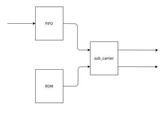
//----------------rd_fifo_en------------------
always @(*) begin
if (state == MODULATE) begin
if (cnt_mapping == 'd5 || cnt_mapping == 'd19 || cnt_mapping == 'd32 || cnt_mapping == 'd46) begin
rd_fifo_en = 1'b0;
end
else begin
rd_fifo_en = 1'b1;
end
end
else begin
rd_fifo_en = 1'b0;
end
end

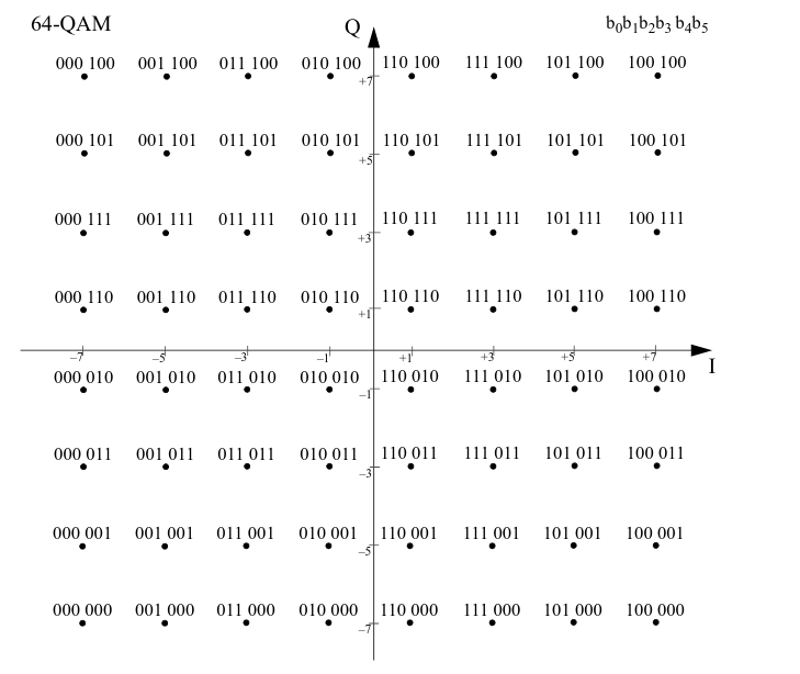
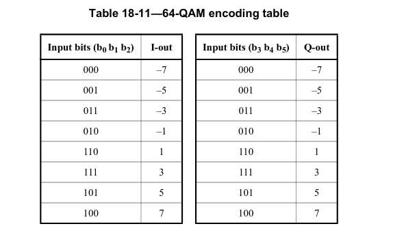
//------------------tx_modulate_re_out----------------
always @(posedge clk_Modulation) begin
if (reset == 1'b1) begin
tx_modulate_re_out <= 'd0;
end
else if(state == MODULATE)begin
// insert pilot according to the pilot index,when rom dout is 1, the inserted pilot is 1 1 1 -1
// when rom dout is 0 the inserted pilot is -1 -1 -1 1
if(cnt_mapping == 'd5 || cnt_mapping == 'd19 || cnt_mapping =='d32)begin
if (rom_dout == 1'b1) begin
tx_modulate_re_out <= QAM64_IQ_ONE;
end
else begin
tx_modulate_re_out <= QAM64_IQ_MINUS_ONE;
end
end
else if (cnt_mapping == 'd46) begin
if (rom_dout == 1'b1) begin
tx_modulate_re_out <= QAM64_IQ_MINUS_ONE;
end
else begin
tx_modulate_re_out <= QAM64_IQ_ONE;
end
end
else begin
case(rd_fifo_dout[5:3])
3'b000: tx_modulate_re_out <= QAM64_IQ_B000;
3'b001: tx_modulate_re_out <= QAM64_IQ_B001;
3'b010: tx_modulate_re_out <= QAM64_IQ_B010;
3'b011: tx_modulate_re_out <= QAM64_IQ_B011;
3'b100: tx_modulate_re_out <= QAM64_IQ_B100;
3'b101: tx_modulate_re_out <= QAM64_IQ_B101;
3'b110: tx_modulate_re_out <= QAM64_IQ_B110;
3'b111: tx_modulate_re_out <= QAM64_IQ_B111;
default : tx_modulate_re_out <= 'd0;
endcase
end
end
else begin
tx_modulate_re_out <= 'd0;
end
end

//------------------tx_modulate_im_out----------------
always @(posedge clk_Modulation) begin
if (reset == 1'b1) begin
tx_modulate_im_out <= 'd0;
end
else if(state == MODULATE)begin
// insert pilot according to the pilot index,when rom dout is 1, the inserted pilot is 1 1 1 -1
// when rom dout is 0 the inserted pilot is -1 -1 -1 1
if(cnt_mapping == 'd5 || cnt_mapping == 'd19 || cnt_mapping =='d32 || cnt_mapping == 'd46)begin
tx_modulate_im_out <= 'd0;
end
else begin
case(rd_fifo_dout[2:0])
3'b000: tx_modulate_im_out <= QAM64_IQ_B000;
3'b001: tx_modulate_im_out <= QAM64_IQ_B001;
3'b010: tx_modulate_im_out <= QAM64_IQ_B010;
3'b011: tx_modulate_im_out <= QAM64_IQ_B011;
3'b100: tx_modulate_im_out <= QAM64_IQ_B100;
3'b101: tx_modulate_im_out <= QAM64_IQ_B101;
3'b110: tx_modulate_im_out <= QAM64_IQ_B110;
3'b111: tx_modulate_im_out <= QAM64_IQ_B111;
default : tx_modulate_im_out <= 'd0;
endcase
end
end
else begin
tx_modulate_im_out <= 'd0;
end
end

always @(posedge clk_Modulation) begin
if (reset == 1'b1) begin
tx_modulate_out_valid <= 1'b0;
end
else if (state == MODULATE) begin
tx_modulate_out_valid <= 1'b1;
end
else begin
tx_modulate_out_valid <= 1'b0;
end
end

endmodule